Pancho Tomov
ORCID iD: 0000-0003-1649-6947
Web of Science Researcher ID: AAH-3804-2019
Technical University of Sofia, Bulgaria
Lubomir Dimitrov
ORCID iD: 0000-0001-8584-5958
Web of Science Researcher ID: AAA-2350-2020
Technical University of Sofia, Bulgaria
https://doi.org/10.53656/adpe-2025.16
Pages 182-189
Abstract. The modern concept of smart cities is a vision for urban development to integrate multiple information and communication technology (ICT) and Internet of Things (IoT) solutions in a secure manner to manage city assets, which include, but are not limited to, information systems of, libraries, transportation systems, hospitals, power plants, water supply networks, waste management and other public services. The goal of building a smart city is to improve the quality of life by using urban informatics and technologies to improve the efficiency of services and meet the needs of residents. ICT is used to improve the quality, efficiency and interactivity of urban services, to reduce costs and resource consumption and to improve the contact between citizens and government. Most smart city concepts rely heavily on the use of innovative technologies involving various modular components that need to be multiplied within the smart environment. This requires building automation systems to increasingly use budget solutions for the implementation of supporting modules. One of the solutions in this area is the use of small-sized and single-chip controllers, as well as intelligent sensors. In the presented article, a concept for controlling mechanical movements based on potentiometric feedback and servomotors used in building automation modules is developed.
Keywords: control systems; electric drive; positional control system; PLC
- Introduction
In modern conditions, energy saving is a key factor in increasing efficiency. One way is to use solar energy through photovoltaic systems to achieve energy-neutral buildings. One of the main problems in urban environments is low productivity due to the peculiarities of the urban environment. One of the approaches is to increase the illumination time of the panels by optimally controlling their position relative to the sun with the use of electromechanical positioning systems. They are based on an electric drive – an electromechanical system for driving the panel’s actuators and controlling the movement to achieve optimal results (Tomov, 2019; Wach, 2011).
Modern electric drive is a set of multiple electrical machines, devices and control systems. This is the main consumer of electrical energy (60%) and the main source of mechanical energy in industry, with engines divided into types:
Unregulated, the simplest, designed to start and stop the movement, operating in a single speed mode; Regulated, designed to control the speed and control the start and stop of the engine for a given process; not automated; automated.
Currently, automated electric propulsion is widely used in all spheres of life and society – from industrial production to everyday life.
- Drive systems
A modern electric drive contains an automatic control system, which in the simplest cases provides starting, shutting down the motor and protecting the drive, and in more complex cases controls the technological process of the driven mechanism.
The angular velocity of a DC motor can be regulated in several ways:
- Regulation by resistance in the armature circuit. This method is used with low quality requirements for speed control indicators, while at the same time it is distinguished by its flexibility and simplicity of implementation.
- Regulation by changing the magnetic flux. It is widely used in electric drives due to its simplicity of implementation and cost-effectiveness, since the regulation is a relatively low-power motor excitation circuit and is not accompanied by large power losses.
- Regulation by changing the armature voltage. The change in rotation speed is carried out in the direction of decrease, since the voltage applied to the armature in most cases can also only change downwards from the nominal. The smoothness of regulation is determined by the smoothness of the change in the supply voltage.
- Pulse regulation. The motor is periodically supplied with voltage pulses of a certain frequency.
Electric drive systems are capable of moving objects of high weight at the required speed. The drive can be carried out either by DC servo motors or by DC stepper motors (Pyrhonen et al., 2016). It can be suitable for both rotational and linear movements. The electric drive system will be ideal for precision applications. Most importantly, it has greater accuracy and repeatability. The only drawback of this system is that it is slightly more expensive.
The panel motion control system is divided into cyclic, positional and contour.
The cyclic system is the simplest, since two positions are usually programmed: the start and end of the rotation.
The position control system sets not only a sequence of commands, but also the position of all nodal points, it is used for complex movements with a large number of positioning points. In this case, the trajectory is not controlled between individual points and can deviate from the straight line connecting these points (Dimitrova et al., 2025).
The contour control system sets the movement in the form of a continuous path or chain and at any moment determines not only the position of the links, but also the speed vector of movement. This system provides movement along a straight line or arc, respectively, by setting two or three points of the trajectory sections. Thus, some parts of the path can be interpolated by circular arcs and linear segments.
- Control Systems
Programmable Logic Controllers are digital computers that use programs designed with ladder logic or function block structures to control the automation of electromechanical processes (Dimitrov et al., 2022). Unlike consumer computers, PLCs are designed to be highly reliable and can operate almost continuously.
Performing the same task as an electrical relay, programmable logic controllers turn on or off the flow of electricity. However, because of the use of logic in response to an almost unlimited amount of real-time values to determine the sequence of electrical flow to be triggered with or without the presence of a human operator (Samanta, 2024).
3.1. Importance and Function of PLC.
The most important aspect of a programmable logic controller is that it can respond to an almost unlimited amount of input data. The only limitation on the capabilities of a PLC comes from the number of sensors placed to supply data to its logic processors and the ability of its logic programmer to anticipate potential circumstances.
PLC logic processors are not capable of making decisions that exceed the parameters of the programmed logic, but unlike electrical relay systems, there is no mechanical limit to the input values a device can receive or the output it can control.
Most PLCs are used in complex systems to respond to real-time values collected from connected sensors. Although they may be designed to interact with a human operator, their ability to use peer-to-peer (P2P) communication with other PLC devices in the system gives programmable logic controllers the ability to respond at the speed of digital processing to vast amounts of real-time data. A PLC using P2P communication can respond faster than any human to real-time situations in complex systems (Fadali & Visioli, 2013). The use of „health checks“ as a standard in PLC programming allows the module to receive initial input values from the system upon power-up to determine whether all hardware in the system is operating properly. These checks are performed in minutes, not hours, which would be required for a human operator to manually perform the same operational checks. For the implementation of budget-oriented control of the photovoltaic panel, it is appropriate to use the widely used Arduino controller.
Microcontrollers are single-chip microcomputers designed to control compact devices. Below is information about the structure and programming of the Arduino UNO microcontroller, which will be used in the model presented in this work.
3.2. Optimal choice of controllers
The choice of control is dictated by the goals, type of activity and conditions for its implementation, as well as the expected final results. A general view of the Arduino UNO controller is presented in Fig. 1 (Moody, 2016).
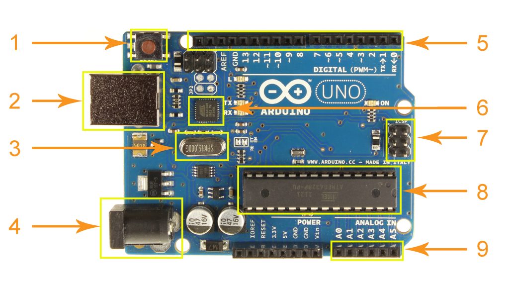
Figure 1. General View of Arduino UNO controller
A draft description of the main components of the controller and their functionality is shown in Table 1.
Table 1. Description of the main components of the ARDUINOr
| № | Description | Value |
| 1 | RESET | |
| 2 | USB port/ Power supply | 5 V |
| 3 | Quartz oscillator | 16Mhz |
| 4 | External power supply | 7 – 12 V |
| 5 | Digital I/O ports. | 40 mA |
| Pins 3, 5, 6, 9, 10 and 11 are marked with a „~“ sign | PWM | |
| 6 | ATmega 16U2 usb to serial converter | |
| 7 | SPI communication | |
| 8 | AТmega 328 processor | |
| 9 | Analog ports | 1024 levels |
Pulse width modulation is a method in which the width (or duty cycle) of the pulses is changed under the influence of the control signal, while their frequency, phase and amplitude remain unchanged. In this case, the control signal is a digital value from 0 to 254, which is supplied by the controller to the PWM modulator.
The narrower the pulses, the smaller the voltage value and vice versa – the larger the value, the wider the pulses (Fig. 2).
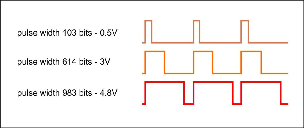
Figure 2. Pulse Width Modulation (PWM)
To control the position of the panel, feedback is used via a potentiometer sensor, the advantages of which are that in the event of a power failure, it retains the position information, since it has an absolute rather than relative position definition. Potentiometers work by changing the position of a sliding contact through a uniform resistance. In the sensor, the entire input voltage is applied along the entire length of the resistor, and the output voltage is the voltage drop between the fixed and sliding contacts. The measured voltage (Output voltage) is proportional to the angular position of the sensor, which is why it is used for comparison with the set desired value (DesVal) in the following fragment:
int potPin = A3;
int potVal = 0; // Variable to store the input from the potentiometer
int DirectPin = 9; // Direction control, connected to digital pin 9
int pwmPin = 10;
int brakePin = 13
// Program variables
int DesVal = 500; // Desired position
void setup()
{
pinMode(DirectPin, OUTPUT); // sets the pins as output
pinMode(pwmPin, OUTPUT);
}
void loop()
{
potVal = analogRead(potPin);
if (potVal = DesVal)
{
digitalWrite(brakePin, HIGH);// Stop motor
}
if (potVal < DesVal)
{
digitalWrite(DirectPin, HIGH)// Set direction
analogWrite(pwmPin, 30)
}
if (potVal > DesVal) // Higest half of potentiometer’s range
{
digitalWrite(DirectPin, LOW)// Set direction
analogWrite(pwmPin, 30)
}
}
An additional useful functionality is the possibility of remote control via a Bluetooth positioning control module, implemented with the fragment shown below1.
#include <Servo.h>
#include <SoftwareSerial.h>
SoftwareSerialbt(3,2);//RX,TX
Servo servo1;
int pos1=90;
void setup() {
servo1.attach(5);
Serial.begin(9600);
}
void loop() {
if (Serial.available()>0){
char veri = Serial.read();
if ( veri==’B’ && (pos1<180)){
pos1 = pos1+1;
servo1.write(pos1);
delay(15);
}
if ( veri==’A’ && (pos1>0)){
pos1 = pos1-1;
servo1.write(pos1);
delay(15);
}
- Conclusion
Solar panels work most efficiently when they are pointed at the sun and their surface is perpendicular to the sun’s rays. Solar panels are usually placed on a roof or supporting structure in a fixed position and cannot follow the position of the sun throughout the day.
Therefore, solar panels are usually not at the optimal angle (90 degrees) throughout the day. The angle between the horizontal plane and the solar panel is usually called the tilt angle. The tilt angle can be in the range of 15 to 90°. A minimum tilt of 15° ensures natural cleaning of the surface of the photovoltaic module from dust during precipitation.
Due to the movement of the Earth around the Sun, seasonal variations also occur. In winter, the angle of incidence of sunlight is much smaller than in summer. Therefore, the tilt angle is essential for efficiency, especially in small individual photovoltaic systems. From this point of view, the application of budgetary solutions for process optimization is of particular importance, since the costs of implementing the control and positioning system should not represent a significant percentage of the overall investment.
Acknowledgments
The authors would like to thank the Research and Development Sector at the Technical University of Sofia for the financial support.
NOTES
- Controlling a Servo Motor via Bluetooth (Arduino UNO/Nano and HC-05). https://forum.arduino.cc/t/controlling-a-servo-motor-via-bluetooth-arduino-uno-nano- and-hc-05/1122759
REFERENCES
Dimitrov, S. B., Totev, D. K., Nikolov, S. N., Dimitrova, R. K. (2022). Design of compost production system powered by green energy sources. 14th Electrical Engineering Faculty Conference (BulEF). https://doi.org/10.1109/BulEF56479.2022.10020204.
Dimitrova, R., Nikolov, S., Tsolov, S., Dimitrov, S. (2025). Мethodology for designing low-cost robots with parallel kinematics. Engineering Research Express, 7(1), 015214. https://doi.org/10.1088/2631-8695/ada5a8.
Fadali, M., Visioli, A. (2013). Digital Control Engineering. Elsevier.
Moody, G. (2016, October 3). Arduino on Arduino battle ends in reconciliation, merger. Ars Technica. https://arstechnica.com /information-technology/2016/10/arduino-on-arduino-battle-ends-in-reconciliation-merger/.
Pyrhonen, J., Hrabovcova, V., Semken, R. S. (2016). Electrical Machine Drives Control. Wiley.
Samanta, B. (2024). Introduction to Digital Control: An Integrated Approach. Springer. https://doi.org/10.1007/978-3-031-66830-2.
Tomov, P. (2019). Sistemi za nabludenie I uprawlenie w mehatronikata. Publishing house of TU Sofia.
Wach, P. (2011). Dynamics and Control of Electrical Drives. Springer.