Reneta Dimitrova
Technical University of Sofia, Bulgaria
Sasho Vazharov
Company “Vanico“ Ltd, Blagoevgrad, Bulgaria
https://doi.org/10.53656/adpe-2025.05
Pages 54-64
Abstract. The purpose of this work is to design and create an automatic machine for simultaneous processing of two parallel surfaces, which will be implemented as an automatic machine with independent drive of one or both spindles in position and speed. The automatic machine will reduce the cost of time and labor, increase productivity and reduce the cost of production. To achieve the goal, have been developed a conceptual diagram of the necessary automation devices, a kinematic diagram of the designed new specialized devices and a manipulation diagram of the automated technological process. 3D models of the automatic machine with the designed specialized feeding device and specialized tightening device have been created. The necessary calculations have been made, and a work cycle diagram has been compiled.
Keywords: automation; prismatic part; simultaneous parallel processing; design
- Introduction
Automation devices and systems are of fundamental importance for production processes. They serve as a basis for the design of new innovative automated technological complexes. Due to the continuous development of technologies and innovations in recent years, automation devices and systems are constantly improving, as well as expanding their capabilities (Mitev & Malakov, 2024). For this purpose, it is necessary to use validated methods (Dichev et al., 2024), methodologies and algorithms (Malakov & Zaharinov, 2012) when designing new automation devices and systems (Mitev, 2024), as well as when modernizing existing ones (Tomov, 2017). The correct application of the toolkit (Vassilev & Komarski, 2024), whether theoretical (Malakov & Zaharinov, 2021) or software (Tomov, 2019) will lead to positive results in automating or modernizing various production processes (Vladimirov et al., 2024). There are various machines for simultaneous machining of two parallel sides of workpieces. For example, disk milling machines are spaced apart with spacers that determine the size of the workpiece or a two-spindle universal milling machine. Machines are also known that can machine rotary workpieces of different configurations. However, an automatic machine for simultaneous machining of two parallel surfaces implemented as an automatic machine with independent drive of one or both spindles in position and speed is not known.
The task is solved by designing an automatic machine for simultaneous parallel processing based on an existing machine with a suitable design for processing rotary parts, by adding another additional spindle. The purpose of the main spindle is changed, and instead of a workpiece, cutting tools are attached to the main and additional spindles.
This automatic machine can process two parallel surfaces of workpieces with dimensions of 3 x 3 x 10 [mm] to 50 x 50 x 100 [mm] without changing the cutting tools. To achieve the set goal, it is necessary to design a specialized feeding device for prismatic parts, as well as a specialized tightening device. The parallelism of the machined surfaces, which should be achieved, must be below 0.01 [mm], and the roughness of the treated surfaces should be 1.25 Ra.
- Conceptual, kinematic and manipulation scheme
Fig. 1 shows the conceptual scheme of the designed automation devices necessary for the implementation of an automatic machine for simultaneous processing of two parallel surfaces of prismatic parts.
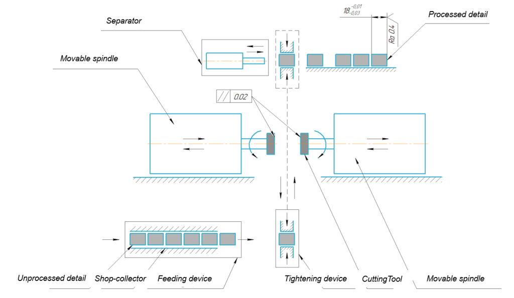
Figure 1. Conceptual scheme
Fig. 2 shows the kinematic scheme of the specialized tightening device, with F a is the cylinder force; S – reactions of the supports and Q – compressive forces, and in Fig. 3 the created manipulation scheme of the process.
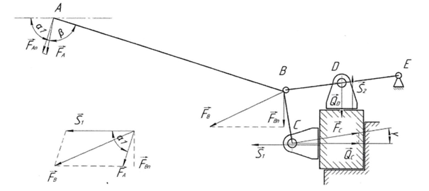
Figure 2. Kinematic scheme of the specialized tightening device

Figure 3. Manipulation scheme
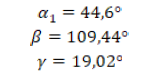
The necessary arm dimensions to ensure normal operation of the tightening device are set as follows:
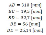
The necessary angles to ensure normal operation of the tightening device are as follows:
The normal force on the cylinder relative to the arm AB is calculated by formula (1):
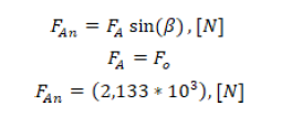
(1)
The horizontal compression of the workpiece Q c is calculated by formula (2) and formula (3):
![]()
(2)
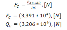
(3)
The vertical pressing of the workpiece Q D is calculated by formula (4) and formula (5):
![]()
(4)
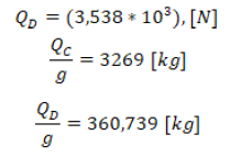
(5)
To determine the force in a straight stroke F p and reverse stroke F o of the tightening device it is necessary to calculate the piston area S 1 and the piston rod S2, depending on the pressure in the cylinder chambers P 1 and P 2 and the diameter of the piston D and the piston rod d, shown in Fig.4.
![]()
(6)
![]()
(7)
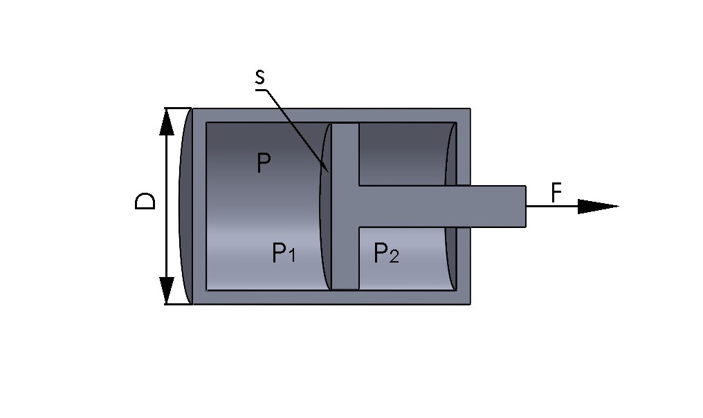
Figure 4. Scheme of tightening cylinder
![]()
(8)
![]()
(9)
![]()
(10)
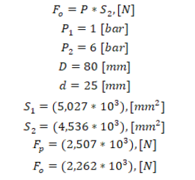
(11)
After the calculations were made, the appropriate tightening cylinder was selected, which will ensure normal operation of the newly designed specialized tightening device.
- Design of an automatic machine for simultaneous processing of prismatic details
Fig. 5 shows typical views of the developed 3D model of the designed automatic machine for simultaneous parallel processing of prismatic parts, and Fig. 6 shows the rendered 3D models of the feeding device and the tightening device. The self-flowing shop-collector stores the unprocessed details in an oriented position in space and are designed with the possibility of mechanical readjustment of the width of the chute depending on their size. At the outlet of the shop-collector, a specialized flow guide plate is attached, to guide the flow, to a separator for feeding the workpiece into the tightening device. The specialized feeding device includes a base on which are attached a separator for feeding the workpiece into the tightening device, limiting plates for the movement of the separator for feeding and a limiter for the end position of the fed workpiece. The first three structural elements are attached to the supporting structure of the shop-collector, and the limiter for the end position is attached by a connecting element to the base for the specialized tightening device.
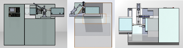
Figure 5. Front, side and top view of the designed automatic machine
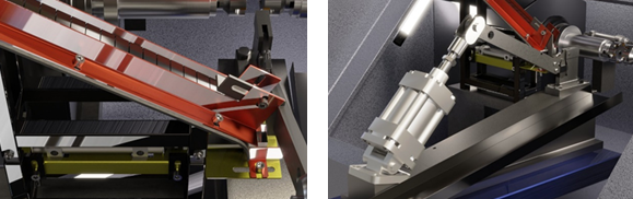
Figure 6. Rendered 3D model of the feeder and the tightening device
The main structural units of the automatic machine are:
- Shop-collector for workpieces.
- Basis of the specialized feeding device.
- Separator for feeding the workpiece into the specialized tightening device.
- Limiting plates for movement of the separator for feeding the workpiece – 2 pcs.
- Limiter for the end position of the fed workpiece.
- Basis for the specialized tightening device.
- Tightening cylinder.
- Lever system, including arm, a guide arm and 2 movable jaws.
- Support fixture.
- Fixed jaws 2 pcs.
- An existing machine.
- Main spindle Z1.
- Additional spindle Z2.
- Movable table along the X axis.
- Control panel.
- Cutting tools – 2 pcs.
- Separator for the removing the processed parts.
- Output Shop-collector for removing the processed parts.
- Cassette for the processed parts.
The specialized tightening device includes a base attached to the movable table along the X axis of an existing machine; a tightening cylinder attached to the base through specialized plates; a lever system connected to the tightening cylinder, including arm, a guide arm and movable jaws holding the fed workpiece.
The last structural unit is a support fixture attached to the base of the tightening device, in which the fixed jaws are also located.
The sequence of the work cycle is as follows:
- The workpieces are stored in an oriented position in a shop-collector for workpieces.
- The movable table along the X axis is in the starting position, namely the lowest position – point 0.
- An unprocessed detail is separated from the general flow by the reverse stroke of a feed separator, the starting position of which is below the shop-collector for workpieces.
- Under the action of its own weight, the workpiece falls onto the base of the specialized feeding device and is fed by the forward stroke of the pneumatic separator until it stops in the support fixture of the specialized tightening device.
- The tightening device is activated, which presses the workpiece and ensures its stationary position.
- The rapid movement of the movable table along the X axis in the working area of the machine follows – point 1.
- A CNC machining program is set from the control panel, and both spindles are activated simultaneously Z1 and Z2.
- After completion of processing, rapid movement of the movable table along the X axis outside the working area of the machine follows – point 2.
- The finished workpiece is released from the tightening device by the reverse stroke of the clamping cylinder.
- A separator is activated to remove the processed parts, which, by moving forward, moves the part to a gravity-fed magazine collector.
- The processed detail is transported under the action of the angle of inclination of the output shop-collector and their own weight and stored in a cassette.
- Then follows a rapid movement of the movable table along the X axis to the starting position, namely the lowest position – point 0.
- After which the work cycle is repeated.
Table 1 shows 3D models of the main structural elements of the designed automatic machine for simultaneous parallel processing of prismatic parts.
Table 1. 3D models of the main structural elements
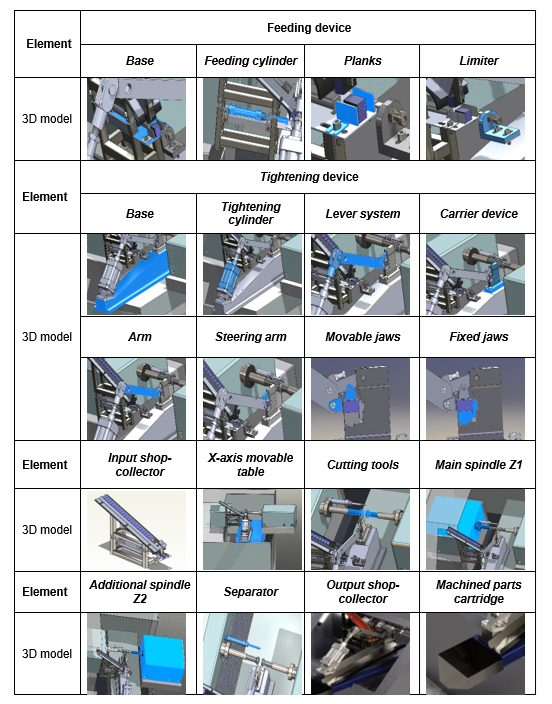
Fig. 7 shows the principle of operation of the designed specialized tightening device in the open and closed position with a workpiece inserted.
The fixed jaws are attached to the support fixture, on which the workpiece is positioned from the feed separator. After tightening, the workpiece is transported to the working area of the technological unit for processing.
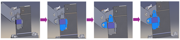
Figure 7. Operating principle of the specialized tightening device
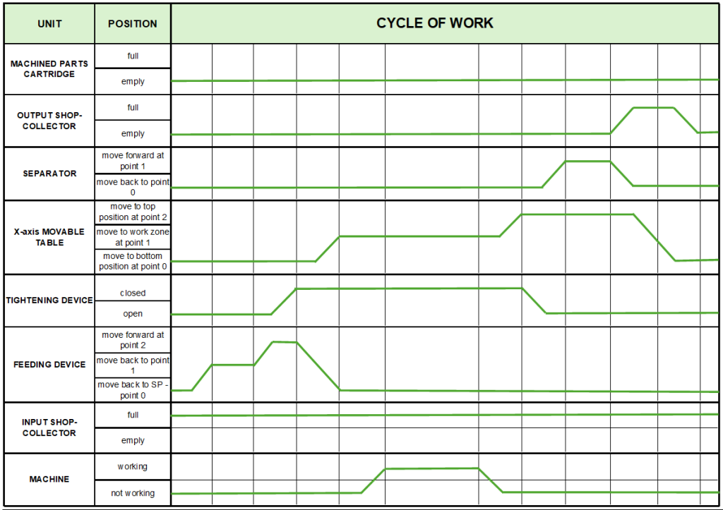
Figure 8. Work cycle diagram of operation
A work cycle diagram of the operation of the designed automatic machine has been drawn up, shown in Fig. 8, which illustrates the times, starting and mutual positions of the structural units relative to each other during one cycle of operation, which is then repeated and is the same until the workpieces in the input shop-collector are exhausted or the output shop-collector is filled with processed parts. In one of the two events, it is necessary to load the shop-collector or replace the machined parts cartridge with an empty one.
- Conclusions
As a result of the design, a virtual prototype of an automatic machine for simultaneous parallel processing of prismatic parts was created. A conceptual scheme of the automatic machine, a kinematic scheme of the designed devices and a manipulation scheme of the automated process were developed. 3D models of the automatic machine, the specialized feeding device and the specialized tightening device with all their structural elements were developed. The necessary calculations were made for the pneumatic cylinders, which will ensure normal operation of the automatic machine. A work cycle diagram of the technological process was compiled.
All structural units are designed with the possibility of mechanical readjustment, which significantly increases the degree of flexibility of the automatic machine and provides the possibility of simultaneous parallel processing of a wide range of workpieces with dimensions from 3 x 3 x 10 [mm] to 50 x 50 x100 [mm] without changing the cutting tools.
The designed automatic machine is applicable for automating production and technological processes dealing with metalworking and manufacturing of various types of parts.
Acknowledgement
This research was funded by the Research and Development Sector at the Technical University of Sofia. The authors thank the Research and Development Sector at the Technical University of Sofia for their financial support.
Dichev, D., Diakov, D., Zhelezarov, I., Valkov, S., Ormanova, M., Dicheva, R., Kupriyanov, O. (2024). A method for correction of dynamic errors when measuring flat surfaces. Journal Sensors Open Access, 24(16). https://doi.org/10.3390/s24165154.
Malakov, I., Zaharinov, V. (2021). Choosing an optimal size range of the product “pipe clamp”. In R. Matoušek, J. Kudela (Eds.), Recent Advances in Soft Computing and Cybernetics (pp. 197 – 213). Springer. https://doi.org/10.1007/978-3-030-61659-5_17.
Malakov, I., Zaharinov, V. (2012). Interactive software system for multicriteria choosing of the structural variant of complex technical systems. Proceedings of the 23rd International DAAAM Symposium “ntelligent Manufacturing & Automation”, 23(1), 199 – 204. https://www.daaam.info/Downloads/Pdfs/proceedings/proceedings_2012/047.pdf
Mitev, P. (2024). Development of a system for the active orientation of small screws. Engineering Proceedings, 70(1), 55. https://doi.org/10.3390/engproc2024070055.
Mitev, V., Malakov, I. (2024). Analysis of the quality of polymer parts for automatic assembly. AIP Conference Proceedings, 3063, 060012. https://doi.org/10.1063/5.0195873.
Tomov, P. (2017). Increasing the efficiency of automation of production processes by reporting the parameters of the parts’ flow. TEM Journal, 6(3), 484 – 487. https://dx.doi.org/10.18421/TEM63-08.
Tomov, P., Dimitrov, L. (2019). The role of digital information models for horizontal and vertical interaction in intelligent production. Facta Universitatis, Series: Mechanical Engineering, 17(3), 397 – 404. https://doi.org/10.22190/FUME190422037T.
Vassilev, V., Komarski, D. (2024). Retrofit of a roundness measuring instrument. 34th International Scientific Symposium Metrology and Metrology Assurance, 1 – 5. https://doi.org/10.1109/MMA62616.2024.10817687.
Vladimirov, B., Nikolov, S., Tsolov, S. (2024). Programming industrial robots in the Fanuc ROBOGUIDE environment. Engineering Proceedings, 70(1), 20. https://doi.org/10.3390/engproc2024070020.
Prof. Reneta Dimitrova, PhD
ORCID iD: 0000-0001-6594-131X
Web of Science Researcher ID: GWZ-2447-2022
Technical University of Sofia
Sofia, Bulgaria
E-mail: rkd@tu-sofia.bg
Sasho Vajarov, Eng
Company “Vaniko” Ltd
Blagoevgrad, Bulgaria
E-mail: Sasho.Vajarov@vaniko.com

Свързани статии:
 THE REFLECTIVE APPROACH TO THE VELOPMENT OF PERSONAL AND SOCIAL COMPETENCES THROUGH LEARNING CONTENT IN THE CONTEXT OF THE REFUGEE PROBLEM FIELD
INCREASING THE LEVEL OF MATHEMATICAL KNOWLEDGE OF FIRST GRADE STUDENTS THROUGH WORKING WITH COLLECTED DATA BY HIMSELF
Medicine and the question of the future
Strategic and Communication Aspects for the Use of Artificial Intelligence in Education
THE REFLECTIVE APPROACH TO THE VELOPMENT OF PERSONAL AND SOCIAL COMPETENCES THROUGH LEARNING CONTENT IN THE CONTEXT OF THE REFUGEE PROBLEM FIELD
INCREASING THE LEVEL OF MATHEMATICAL KNOWLEDGE OF FIRST GRADE STUDENTS THROUGH WORKING WITH COLLECTED DATA BY HIMSELF
Medicine and the question of the future
Strategic and Communication Aspects for the Use of Artificial Intelligence in Education
