Dobri Komarski
ORCID iD: 0000-0002-6838-4608
Web of Science Researcher ID: MFK-2231-2025
Technical University of Sofia, Bulgaria
Velizar Vassilev
ORCID iD: 0000-0003-1563-2353
Web of Science Researcher ID: X-7785-2018
Technical University of Sofia, Bulgaria
Hristiana Nikolova
ORCID iD: 0000-0003-0484-9709
Web of Science Researcher ID: DKA-0419-2022
Technical University of Sofia, Bulgaria
https://doi.org/10.53656/adpe-2025.09
Pages 98-108
Abstract. Neural networks are fundamental concept in artificial intelligence and machine learning, inspired by the structure and function of the human brain. A neural network is a computational model composed of interconnected nodes (called neurons or units) organized in layers. These networks are designed to recognize patterns, learn from data, and make predictions or decisions.
As a part of the neural networks, mechanical neural networks are physical systems designed to mimic the behavior of artificial neural networks using mechanical components. These systems leverage the properties of materials and structures to process information, adapt to external stimuli, or perform tasks such as pattern recognition, optimization, or control.
The developed surface-shaping mechanical neural network is based on systems with parallel kinematics but in addition contains sensing elements part of the electronic system controlled by developed software. The system can adapt its surface geometry depend on the external stimuli, in this case the force applied on it.
Keywords: mechatronic; neural network; flexure; rotation; surface-shape; parallel kinematic
- Introduction
Mechanical neural networks bridge the gap between classical mechanics and modern control theory, enabling systems that adapt in real-time to dynamic environments. By combining analytical models (e.g., differential equations) with computational tools (e.g., machine learning), they offer unprecedented flexibility for applications in aerospace, robotics, and energy (Lee, 2022).
The mechanics of the system is based on the manipulators with parallel kinematics (e.g. Stewart Platform) in this case with 3 movable legs (tripods). The system contains 24 tripods that are connected to each other through flexures and stepper motors. The overall design is shown on Fig. 1.
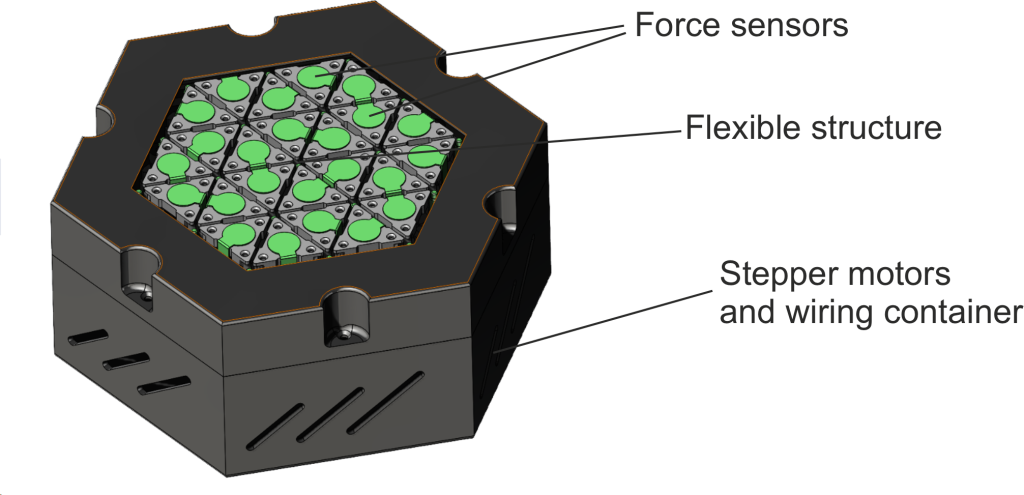
Figure 1. The developed mechanical neural network
Unlike the hexapods (e.g. Stewart Platforms) and delta robots where the moving armes (legs) are six, there are many constructions using three movable arms to obtain spatial motion. These mechanisms are not so complex as hexapods and they find applications in various industry like biomedicine, machine tools, positioning systems, etc.
Tripods, typically have 3-DOF (translation in X, Y, Z) or up to 6-DOF if rotational joints are added to each leg. Each leg contributes to controlling the position of the moving platform (Nikolov et al., 2022; Nikolov et al., 2024; Stoimenov et al., 2024).
3-Leg Parallel Mechanism has simpler design: Fewer legs and actuators reduce mechanical and control complexity and they are easier to design: Inverse kinematics is simpler due to fewer interdependent variables (Bonev, 2008). Compared to the hexapod systems, tripods have lower precision, fewer legs mean less redundancy, making the system more sensitive to errors in individual actuators and reduced stability – less load distribution compared to 6-leg systems. They are lightweight and simpler for calculation (Dimitrova et al., 2025; Gallardo-Alvarado, 2016; Gogu, 2008).
For the improvement of the precision of the parallel kinematic system, it is required the sources of play and friction in the joints and actuators to be eliminated. Therefore, the traditional bearings are replaced by flexure-based equivalents to enable motion, which rely on elastic deformation of slender elements, instead of tribological contacts. The flexure-based design also is capable of reaching higher speed and acceleration of motions due to the lack of friction (the friction is on an atom level).
The applications of the mechanical neural networks could be in a different areas and purposes like in robotics for adaptive grippers, soft robots that adapt to different tasks or environments; Metamaterials for tunable stiffness, vibration control; Structural Engineering for adaptive buildings, earthquake-resistant structures; Biomechanics for prosthetics, wearable devices; Computing for mechanical logic gates, analog computing; Impact-absorbing materials or morphing wings for aircraft; Wearable Technology for clothing or exoskeletons that adapt to the user’s movements (Gogu, 2009; Kong & Gosselin, 2007).
- Key Components of the Neural Networks Structure
Neurons (Nodes) – Basic units of computation in a neural network. Each neuron receives input, processes it using an activation function and produces an output. In this case input value is given by the force sensors – when one or multiple force sensors are activated, the surface is changing using the stepper motors (Lee, 2022; Merlet, 2008).
Input Layers – Receive the initial data. In this case the input layers are the force sensors.
Hidden Layers – Intermediate layers where computation, feature extraction occurs, or reaction is accumulated/transferred. In this case these are the elastic elements that transfer the calculated transition.
Output Layers – Produce the final result. In this case these are the stepper motors that are changing the shape of the surface according to the input values.
Weights and Biases – Weights determine the strength of connections between neurons. Biases allow the model to adjust the output independently of the input. Based on the created computable model, the coordinates and the values of the input force are transferred to motor movements e.g. changing of the shape of the surface
Activation Function – Calculates the output of the node based on its individual inputs and decides whether a neuron should be activated or not. This means that it decides whether the neuron’s input to the network is important or not.
Loss Function – Measures the difference between the predicted output and the actual target.
Optimization Algorithm – Adjusts weights and biases to minimize the loss function.
- Design of the Neural Network Structure
Important characteristics of the current neural network structure is the flexibility of the independent feature of the surface, in this case the shape is triangles. Flexure elements are in the form of leaf springs, in this case 2 relatively long (5 mm) leaf springs. In order to be capable to obtain different angles and shapes, all triangles are connected each other but they move independently.
The theoretical structure has n-numbers of triangles and n-numbers of stepper motor. These numbers depend on the needed surface area. In this study case the numbers of the triangles are 24 and the numbers of the used stepper motors are 19 (Tsolov et al., 2024; Vose et al., 2013). The surface of the structure is almost 64 cm2 (Fig. 3).
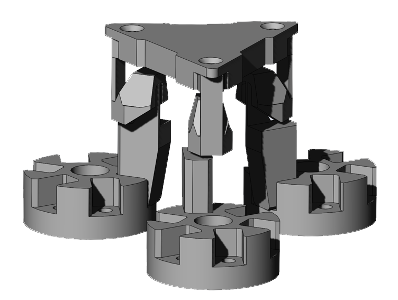
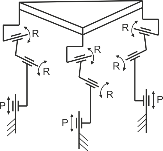
Figure 2. The developed tripod and its kinematic scheme
Design of the flexure provide rotations but is stiff in vertical direction in order to withstand different vertical forces that can be calculated trough the sensors. One of the goals of the design was this system to be able to be produced with 3D printing technology, so all the components including the elastic guides are designed with this in mind (Zagorski et al., 2022).
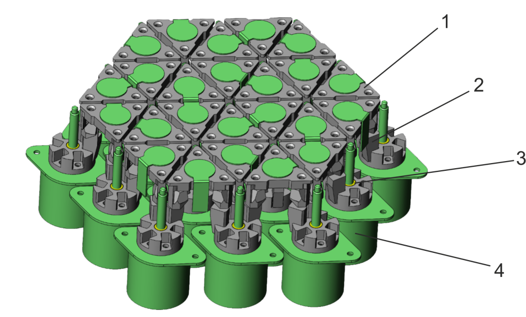
Figure 3. Design of the flexure-based structure
The network consists 24 tripods (Fig. 3) that are able to perform movement along 3 axis (3-DOF). The equivalent simplified parallel kinematic scheme (Fig.2) is 3-PRR mechanism (P – prismatic R – revolute), although relatively long leaf springs have more complex behavior in terms of rotation from one fixed or movable rotation point to two points of rotation depend on the form, stress and deformations.
Assembly of the flexure-based structure contains: Platforms in the form of triangles (pos. 1) that can be positioned in a different angle; Flexures (pos. 2); Nuts with threads that are moved via screws (pos. 3) mounted on stepper motors (pos. 4).
With rotation of the stepper motors the flexures are moved in different vertical positions and depend on the displacement the triangles are moved in different angle. All triangles togethers (the smallest segment) are part of a neural network that can change its surface shape depending on the provided input (in this case the multiple force sensors).
Motions and control of the system are implemented through multiple ESP32 microcontrollers and arrays of force sensors and stepper motors attached to them. The stepper motors are driven by TMC2209 stepper motor drivers. One of the key features of these drivers is the DIAG (diagnostic) pin, which allows the system to detect the end position without using additional limit switches. These ESP32 units communicate with a Raspberry Pi via a USB serial interface. The role of the Raspberry Pi is to processes the input form the microcontrollers and to determine the precise rotation needed for the stepper motors.
- Simulation analysis
Elastic compliant mechanisms usually have limited motions due to the limited working range of the elastic elements. The system should be capable of relatively large displacement so the design of the flexure was an essential part of the development in order to provide the required motions.
The working range is limited by the thickness h of the flexures and its length. This dependence of the flexure’s thickness and the working range can be taken from the equation for calculating the maximum displacement that a given flexure can withstand depending on the material (1):
![]()
(1)
The dependence shows that the smaller the size for h at the given length L, the larger is the angle at which the flexures can be deformed (Diakov et al., 2021; Dichev et al., 2023).
The aim of the next analysis is to show how capable is the system in term of motions e.g. motion limits. The study is performed with CAD software using finite element analysis (FEA). The study scheme replicates the movements and deformations in the real application as close as possible in order to provide reliable results (Fig. 4).
On fig. 5 is shown only one of the possibilities of movement of the system, but the results of the study can show what are the motion limits and shape of the surface.
Actually, the most important is the motion limits between two stepper motors close each other as this is where it has larger deformations e.g. larger stresses.
Another point of interest is if there are different limitations in case the surface has convex or concave shape.
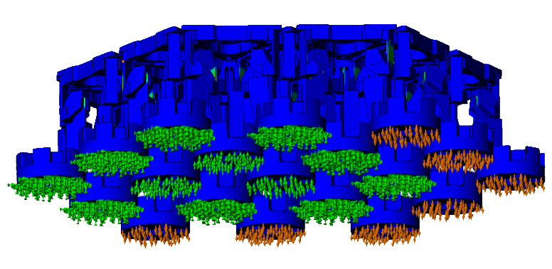
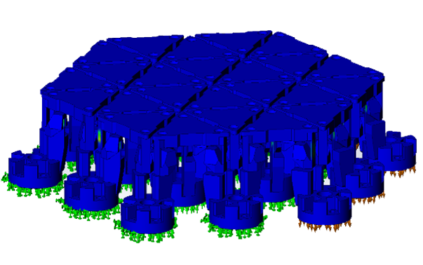
Figure 4. Motion limits analysis scheme
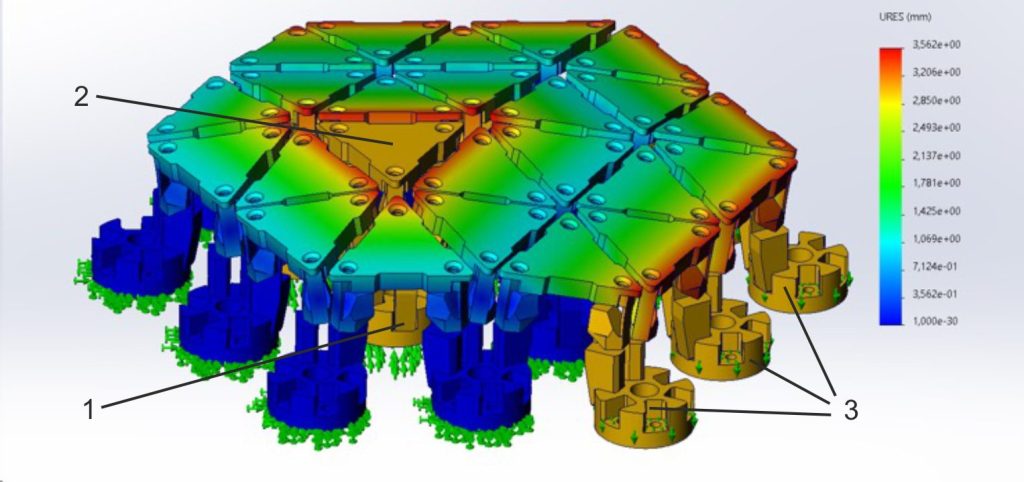
Figure 5. Deformation picture of the study – convex shape
In the first study case (fig. 5) the desired shape is convex. One of the triangles has light pressure force on it and needs to move upwards, of course there will be similar deformation if the triangle stays in position and all other triangles are moved down (all motors are activated and all legs of the tripods are moved down according to the desired shape). In this particular study case, the three legs of the tripod that is pressed are activated and moved up with 3 mm (pos. 1), the “middle ring” of tripods (pos. 2) are fixed and all outer legs of the tripods are moved down with 3 mm (pos. 3).
This means that the displacement along Z axis between two adjacent translation movement axes (stepper motor axes) is 3 mm and the maximum displacement of the legs is 6 mm. The result is a simple convex shape with angle of approximately 9° between the horizontal segment and the others. Factor of safety in this study case with material PA6 is more than 2 (Kotseva et al., 2024; Todorov et al., 2024).
The FEA study of the movement of the legs along Z axis is performed with 3 mm as this is the required amount of movement but in order to understand the maximum allowable displacement along Z axis between two adjacent translation movement axes (stepper motor axes), a study in such a case was performed. With maximum displacement the factor of safety (FOS) should be more than 1.1. In such a case when FOS = 1.1, the system is capable to move along Z axis between two adjacent translation movement axes with 5.5 mm and angle between the horizontal triangle and the others in approx. 9°. This is relatively large displacement for such a flexure-base design (Dichev et al., 2024).
The elastic mechatronic system needs to move not only in convex shape but to concave shape as well, so a study to analyze the maximal allowable movement of the legs along Z axis is performed.
In this study case the same legs are fixed like the previous study (Fig. 5) but the legs that were moved up (+Z direction) are moved down (-Z direction) and the others are moved in opposite direction as well.
Deformation picture is shown on Fig. 6.
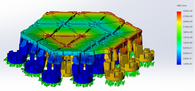
Figure 6. Deformation picture of the study – concave shape
In this study case where a concave shape is required, the design is more restricted due to the distance between the triangles. The developed flexures can provide more than 5.5 mm movement of the legs along Z axis but the triangles are pressed each other before reaching this distance. The results show that the maximum displacement along Z axis in case the needed shape is concave is 2.7 mm when the distance between two triangles is 1.2 mm. In case more displacement is needed, the distance between triangles need to be enlarged.
This difference in motion capability along Z axis between concave and convex shape is due to the design of the surface and is captured in the developed control software in order to prevent collisions or damage of the flexure.
Allowable distance between two adjacent legs (e.g. stepper motors) in case concave shape is formed is 2.5 mm and in case convex shape is formed – 3 mm (Dichev et al., 2016; Dichev et al., 2019).
Case study where the surface is flat but inclined is perform as well (Fig. 7). As the displacement along Z axis is limited to 3 mm the maximum angle that the surface can achieved is 9°. This angle can be enlarged to 17° as the maximum permissible displacement of the legs (e.g. stepper motor) is 5.5 mm and it can be used in case such a surface shape is needed (Diakov, 2021; Dichev et al., 2021).
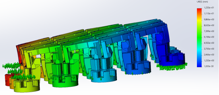
Figure 7. Deformation picture of the study – inclined surface
- Conclusions
The results of the motion analysis confirm that the developed surface-shaping mechatronic neural network can provide different configuration of its surface – convex, concave or any random positions.
Depending of the shape the maximum displacement between two adjacent legs (e.g. stepper motors) for convex shape is maximum 3 mm and for concave shape is maximum 2.5 mm. This is considered during the development of the software.
Maximum angle between the triangles is 9°, but this can be set to 17° only in convex shape if needed as the design can move along Z axis (convex shape) up to 5.5 mm. This is applicable also if the system needs to be set to a relatively flat inclined surface.
The system can move along Z axis up to 20 mm, but this can be adjusted depending how long is the travel of the linear actuators.
These results take into account the calculated factor of safety and maximum allowable movement due to the distance between the triangles.
The area, the size and numbers of the triangles of the neural network can be adjusted to adapt to a specific application.
Acknowledgement
The results in this study were obtained under project No. 251ПР0013-06, funded by the research grant at the Technical University of Sofia. The authors thank the Research and Development Sector at the Technical University of Sofia for their financial support.
REFERENCES
Bonev, I. (2008). Direct kinematics of zero-torsion parallel mechanisms. Proceedings of IEEE International Conference on Robotics and Automation, 3851 – 3856. https://doi.org/10.1109/ROBOT.2008.4543802.
Diakov, D., Komarski D., Nikolova H. (2021). Optimization of Butterfly Flexures for Angular Positioning. 31st International Scientific Symposium Metrology and Metrology Assurance, 1 – 6. https://doi.org/10.1109/MMA52675.2021.9610833.
Diakov, D. (2021). Measurement of Location Deviations of Flat Surfaces. 31st International Scientific Symposium Metrology and Metrology Assurance. https://doi.org/10.1109/MMA52675.2021.9610893.
Dichev, D., Kogia, F., Koev, H., Diakov, D. (2016). Method of Analysis and correction of the Error from Nonlinearity of the Measurement Instruments. Journal of Engineering Science and Technology Review, 9(6), 116 – 121. https://doi.org/10.25103/jestr.096.17.
Dichev, D., Zhelezarov, I., Karadzhov, T., Madzharov, N., Diakov, D. (2019). Method for Measuring Motion Parameters of Moving Objects. Vide. Tehnologija. Resursi – Environment, Technology, Resources. 12th International Scientific and Practical Conference, 3, 27 – 31. https://doi.org/10.17770/etr2019vol3.4131.
Dichev, D., Diakov, D., Dicheva, R., Zhelezarov, I., Kupriyanov, O. (2021). Analysis of instrumental errors influence on the accuracy of instruments for measuring parameters of moving objects. 31st International Scientific Symposium Metrology and Metrology Assurance. https://doi.org/10.1109/MMA52675.2021.9610855.
Dichev, D., Zhelezarov, I., Diakov, D., Dicheva, R., Kupriyanov, O., Malakov, I., Anastasov, K., Valkov, S., Petrov, N. (2023). Mathematical Model for Increasing Accuracy when Measuring Linear Quantities in Conditions of External Mechanical Impacts. 33rd International Scientific Symposium Metrology and Metrology Assurance. https://doi.org/10.1109/MMA59144.2023.10317908.
Dichev, D., Diakov, D., Zhelezarov, I., Valkov, S., Ormanova, M., Dicheva, R., Kupriyanov O. (2024). A Method for Correction of Dynamic Errors When Measuring Flat Surfaces, Sensors, 24(16). https://doi.org/10.3390/s24165154.
Dimitrova, R., Nikolov, S., Tsolov, S., Dimitrov, S. (2025). Methodology for designing low-cost robots with parallel kinematics. Engineering Research Express, 7(1), 015214. https://doi.org/10.1088/2631-8695/ada5a8.
Gallardo-Alvarado, J. (2016). Kinematic Analysis of Parallel Manipulators by Algebraic Screw Theory. Springer.
Gogu, G. (2008). Structural Synthesis of Parallel Robots. Part 1: Methodology. Springer.
Gogu, G. (2009). Structural Synthesis of Parallel Robots. Part 2: Translational topologies with Two and Three Degrees of Freedom. Springer.
Kong, X., Gosselin, C. (2007). Type Synthesis of Parallel Mechanisms. Springer.
Kotseva, G., Kandeva, M., Stoimenov, N., Zagorski, M. (2024). Wear at Boundary Friction of 3D Printed Polymers and Composites. 10th International Conference on Control, Decision and Information Technologies, 473 – 478. https://doi.org/10.1109/CoDIT62066.2024.10708489.
Lee, R. (2022, October 19). A new type of material called a mechanical neural network can learn and change its physical properties to create adaptable, strong structures. The Conversation. https://theconversation.com/a-new-type-of-material-called-a-mechanical-neural-network-can-learn-and-change-its-physical-properties-to-create-adaptable-strong-structures-192800?utm_source=clipboard&utm_medium=bylinecopy_url_button.
Merlet, J. (2008). Parallel Robots. (2nd ed). Springer.
Nikolov, S., Dimitrova, R., Dimitrov, S. (2022). Using of 3D Printing Technologies in the Manufacture of Mechatronic Products. 13th National Conference with International Participation (ELECTRONICA). https://doi.org/10.1109/ELECTRONICA55578.2022.9874404.
Nikolov, S., Dimitrova, R., Tsolov, S., Dimitrov, L. (2024). Classification of Parallel Kinematics Robots. AIP Conference Proceedings, 3063(1), 060001. https://doi.org/10.1063/5.0195795.
Stoimenov, N., Kandeva, M., Zagorski, M., Panev, P. (2024). Static and Kinetic Friction of 3D Printed Polymers and Composites. Tribology in Industry, 46(1), 97 – 106. https://doi.org/10.24874/ti.1546.08.23.10.
Todorov, T., Bankov, B., Zagorski, M., Gavrilov, T., Dimitrov, K. (2024). Rapid Prototyping and Measuring Assessment of a Complex Geometry. 34th International Scientific Symposium Metrology and Metrology Assurance. https://doi.org/10.1109/MMA62616.2024.10817673.
Tsolov, S., Dimitrova, R., Nikolov, S. (2024). Problems in Designing Robots with Parallel Kinematics. Engineering Proceedings, 70(1). https://doi.org/10.3390/engproc2024070005.
Vose, T., Turpin, M., Dames, P., Umbanhowar, P., Lynch, K. (2013). Modeling, design, and control of 6-DoF flexure-based parallel mechanisms for vibratory manipulation, Mechanism and Machine Theory, 64, 111 – 130. https://doi.org/10.1016/j.mechmachtheory.2012.12.007.
Zagorski, M., Sofronov, Y., Ivanova, D., Dimova, K. (2022). Investigation of different FDM/FFF 3D printing methods for improving the surface quality of 3D printed parts. AIP Conference Proceedings, 2449, 060001. https://doi.org/10.1063/5.0090805.