Ivo Malakov
ORCID iD: 0009-0007-3551-6890
Web of Science Researcher ID: FMK-1787-2022
Technical University of Sofia, Bulgaria
Velizar Zaharinov
ORCID iD: 0009-0003-1671-4040
Web of Science Researcher ID: EHJ-1621-2022
Technical University of Sofia, Bulgaria
https://doi.org/10.53656/adpe-2025.08
Pages 83-97
Abstract. This article discusses solving the problem of choosing an optimal structural variant of an automated assembly system for the assembly of a “Brush holder”. Based on a developed technological process for assembling the product, the partial functions of the assembly system are determined, and alternative variants are developed for their implementation. The set of possible structural variants is constructed, taking into account the compatibility between the devices and the possibility of performing more than one partial function by one device, i.e. the presence of polyfunctional devices. The problem of selecting an optimal structural variant is formulated, the set of criteria for evaluating the alternative variants and the constraints are determined. A mathematical model of the optimization problem is constructed. The formulated multicriteria optimization problem is solved both with equivalent objective functions, and with different priorities.
Keywords: design; assembly automation; structural variant; multicriteria optimization; mathematical model; application software
- Introduction
In the current conditions of heightened competition, caused by the globalization of the world economy and dynamically changing market and international relations, industrial companies are forced to continuously increase their efficiency and competitiveness. These conditions place high demands not only on the quality and cost of manufactured products, but also on the means of their production – on the one hand, their complexity is increasing, and on the other hand, the time and costs of their design, development and implementation must be reduced (Pahl et al., 2007; Konold et al., 1997). This is especially true for modern automated assembly systems (AAS), which are complex technical systems, and the creation of which requires significant costs (Boothroyd, 2005; Holle, 2002; Hesse, 1993; Lotter, 1986).
The object of consideration is an assembly system for automated assembly of the product “Brush Holder” (Fig. 1), which is part of the structure of DC motors. The object is particularly suitable for automated assembly, as it is characterized by a relatively large production program – 600,000 pcs./year and an estimated market life of not less than 3-4 years without significant design changes.
The implementation of AAS will lead to an increase in the quality of assembled units, ensuring the necessary productivity in conditions of labor shortage, reducing scrap and cost, improving technical safety and working conditions.
One of the main problems that are solved in the process of designing technical systems is the problem of choosing an optimal structural variant (Mitev, 2024; Todorov et al., 2024; Malakov et al., 2023; Dichev et al., 2017), which significantly determines the efficiency of the designed system. This problem is particularly important, as it forms the basis for further design, and correcting an incorrectly chosen solution at a later stage is associated with significant costs.
Therefore, this article is devoted to the problem of choosing the optimal structural variant of an automated system for assembling the “Brush holder” product.
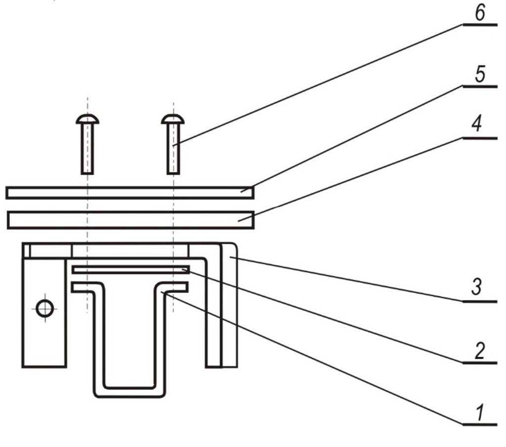
Figure 1. Brush holder assembly

1 – socket; 2 – plate; 3 – holder; 4, 5 – insulator; 6 – rivet (4 pcs.)
- Developing the set of possible structural variants
The general function of the AAS is „Assembling a „Brush holder“ from the component parts under specified quality and productivity requirements“. Based on a developed technological process and the determined type, sequence and division of technological operations by work positions, the general function of the AAS is decomposed into the following partial functions ![]() : – assembling parts “Socket” and “Plate”;
: – assembling parts “Socket” and “Plate”; ![]() – assembly of the “Holder” part;
– assembly of the “Holder” part; ![]() – assembly of the “Insulator” part – 2 pcs.;
– assembly of the “Insulator” part – 2 pcs.; ![]() – assembly of the “Rivet” part – 4 pcs.;
– assembly of the “Rivet” part – 4 pcs.; ![]() – transportation;
– transportation; ![]() – calibration and riveting.
– calibration and riveting.
Variants of devices are developed, representing working positions of the automated assembly system, ![]() for performing each partial function
for performing each partial function ![]() where
where ![]() ;
; ![]() . A description of the variants is presented in Table 1. As can be seen from the table, some of the alternative variants are polyfunctional devices that perform more than one partial function of the system. These are devices
. A description of the variants is presented in Table 1. As can be seen from the table, some of the alternative variants are polyfunctional devices that perform more than one partial function of the system. These are devices ![]() ,
, ![]() , and
, and ![]() , since
, since ![]() perform the partial functions
perform the partial functions ![]() and
and ![]() and
and ![]() perform
perform ![]() and
and ![]() performs
performs ![]() and
and ![]() and
and ![]() performs
performs ![]() and
and ![]()
Table 1. Operating principle of working positions
| Elementary device (working position) |
Method of operation |
| From a gravity feed track, a vibratory feed track and an escapement for sequential feeding, a “Socket” part is picked up, transferred and placed in the assembly fixture by an assembly unit made up of 2 linear pneumatic modules, with a U-shaped cycle. In the same cycle, during the reverse stroke of the escapement, a “Plate” part is separated and fed from a vertical gravity feed track. The part is placed in the fixture by means of an assembly unit on the already placed “Socket” part. | |
| The operation of this elementary device is similar to the operation of the |
|
| The feeding of parts “Socket” and “Plate” is similar to the |
|
| A “Holder” part is fed from a vertical gravity feed track into a slot of an escapement, which orients it secondarily and feeds it to the assembly unit, made up of 2 linear pneumatic modules, with a U-shaped cycle. The assembly unit grabs the part and installs it in the assembly fixture on the placed “Socket” and “Plate” parts. | |
| The “Holder” part is arranged in a pallet placed on a single-axis palletizing station. The gripping, transferring and positioning of the part is performed by an assembly manipulator with 15 positioning points. | |
| From a vibratory feed track, the “Holder” part enters a special slot of an escapement, which feeds it to the assembly unit, made up of 2 linear pneumatic modules, with a U-shaped cycle. It grabs it, transfers it and installs it in the assembly fixture. | |
| The feeding of a “Holder” part to one of the working points of the assembly unit is similar to that of the |
|
| The part “Holder” is palletized in a stationary pallet, from where it is picked up, transported and placed in the assembly fixture by the assembly unit. The feeding and placement of 2 pcs. of “Insulator” part is similar to the |
|
| After assembling the “Insulator” parts, similar to the |
|
| The “Insulator” parts arrive from vertical gravity feed tracks and, through an escapement, are assembled in the working area of the assembly unit, made up of pneumatic modules, with a U-shaped cycle. The assembly unit grabs the parts and places them in the fixture. | |
| The “Insulator” parts come from vertical gravity feed tracks and, through an escapement, are fed into the working area of the assembly unit, made up of pneumatic modules, with a U-shaped cycle. The assembly unit sequentially places the parts in the fixture. | |
| The “Insulator” parts are fed from vertical gravity feed tracks and are assembled by an escapement at one of the working points of the assembly unit. The latter grabs them and places them in the fixture. Within the cycle, at two other working points of the manipulator, two rivets are simultaneously placed by a special head in the holes of the assembled parts. The rivets are fed from a vibratory feed conveyor and an escapement. | |
| Using a vibratory feed conveyor with an escapement and an assembly unit, built from pneumatically driven modules, two rivets are simultaneously placed in the first two holes of the assembled parts and two more rivets on the second stroke of the special head. | |
| By means of an assembly unit, built up of 3 linear modules with pneumatic drive, one rivet is sequentially placed in all holes of the assembled parts. The rivets are fed into a special head by a vibratory feed conveyor and an escapement. | |
| This device is based on a 12-position indexing table, 4 control positions and a fixed cam for pushing the catchers of the assembly devices. | |
| This device is implemented on the basis of a linear synchronous transport system, 4 control positions, 36 assembly devices and a device for pushing the catchers of the assembly devices. | |
| The calibration of the assembly and the formation of the closing heads is performed by a hydraulic press using a special tool. The assembly is introduced into the working area of the tool by one arm of a robot built from pneumatically driven modules, and the calibrated and riveted assembly is removed by the second arm of the robot. | |
| A robot, made up of 3 pneumatically driven modules, picks up an assembled unit and transfers it from the assembly fixture to a special self-unloading tool that calibrates and forms the rivet closing heads. |
The set of possible structural variants ![]() that perform the general function of the assembly system is presented in Fig. 2 in the form of a network model. The elementary devices
that perform the general function of the assembly system is presented in Fig. 2 in the form of a network model. The elementary devices ![]() are arranged in 6 columns in accordance with the partial functions
are arranged in 6 columns in accordance with the partial functions ![]() they perform. The possibilities for combining the elementary devices
they perform. The possibilities for combining the elementary devices ![]() into structures
into structures ![]() that perform the general function of the assembly system are shown by arrows. Each path connecting the beginning (B) and the end (E) of the network model represents a possible structural variant.
that perform the general function of the assembly system are shown by arrows. Each path connecting the beginning (B) and the end (E) of the network model represents a possible structural variant.

Figure 2. The set of possible structural variants
- Statement and mathematical model of the problem of choosing an optimal structural variant
The choosing of an optimal structural variant is related to solving the following problem (Malakov et al., 2023):
With a developed functional structure of the AAS and the alternative devices for performing its partial functions determined, such a compatible combination of them must be determined, performing the general function of the system, which satisfies previously set requirements and conditions (constraints) to the technical and economic characteristics of the system.
After consultations with the client, the following requirements and constraints have been determined for the designed system: minimizing the production cost, energy consumption, labor intensity and price of the assembly system, and its area should not be larger than 6,3 m2.
Taking into account the requirements and constraints of the client, the mathematical model of the formulated problem for choosing an optimal structural variant has the form:
To find a variant ![]() performing the general function of the assembly system, for which:
performing the general function of the assembly system, for which:
![]()
(1)
satisfying the constraint:
![]()
(2)
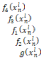
Table 2. Values of the technical and economic characteristics of the elementary devices that make up the AAS variants for assembling the brush holder unit
| l
n |
1 | 2 | 3 | 4 | 5 | 6 |
| 1 | 5 464
6 299,37 4,519 0,509 0,91 |
4 862
6 446,52 4,303 0,497 0,91 |
9 268
10 934,73 7,760 0,866 1,79 |
13 932
11 042,69 8,861 0,058 1,56 |
26 110
10 970,06 14,689 0,427 6,44 |
|
| 2 | 4 699
4 702,64 3,622 0,322 0,91 |
11 270
4 614,10 6,620 0,525 2,34 |
4 852
4 448,81 4,202 0,335 0,91 |
8 401
11 589,10 8,050 0,852 1,79 |
30 156
12 607,401 17,844 1,358 6,44 |
15 110
11 637,32 9,802 0,326 1,56 |
| 3 | 4 328
7 146,35 3,752 0,309 0,91 |
4 357
7 157,21 4,145 0,450 0,91 |
10 092
7 965,13 7,887 1,369 1,79 |
|||
| 4 | 6 413
916,84 4,445 1,050 0,52 |
6 367
1 068,14 4,968 1,775 0,65 |
6 413
916,84 4,445 1,050 0,52 |
|
||
| 5 | 7 469
16,63 1,593 0,023 1,17 |
10 679
22,52 4,899 0,219 1,95 |
7 469
16,63 1,593 0,023 1,17 |
|||
| 6 | 18 679
161,70 10,854 1,483 1,63 |
19 301
190,58 10,234 1,761 1,63 |
18 679
161,70 10,854 1,483 1,63 |
- Solving the problem
The set of structural variants of the AAS is decomposed into 6 subsets. Each subset contains only compatible elements. This allows the application of conventional optimization methods. The total number of possible structural variants of the designed assembly system is 220. To determine the limits of variation (upper and lower bounds) of the objective functions, 48 single-criteria optimization problems are solved, and to find a solution to the multi-criteria problem, it is necessary to solve 6 multi-criteria problems (one for each subset). The decomposition of subsets and the solution of single- and multi-criteria problems are performed using the dialog system for discrete multi-criteria optimization PolyOptimizer (Malakov et al., 2023).
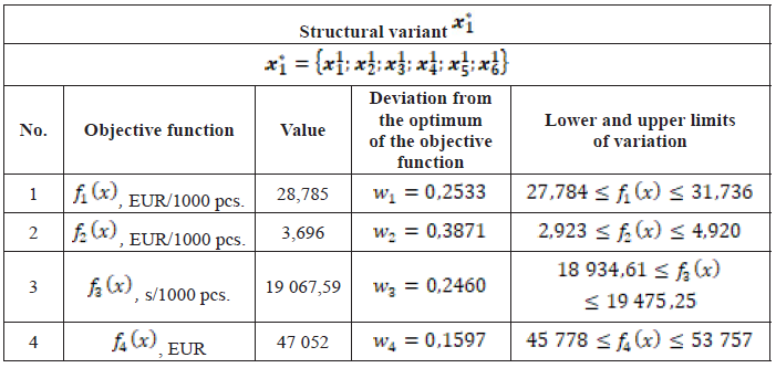
4.1. Solution with equal priority of the objective functions
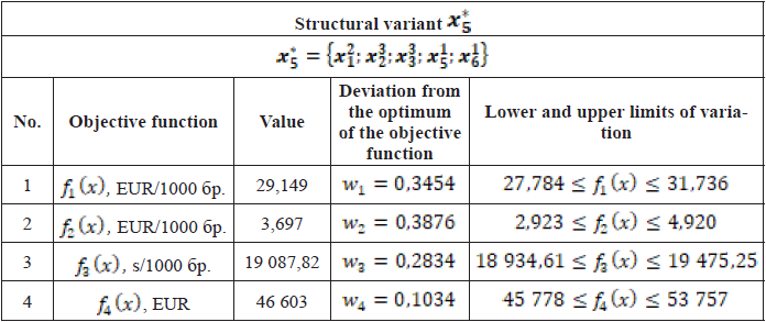
The compromise solution to the problem is found with equal priority of the objective functions. Table 3 shows the values of the objective functions for the solution variant, the devices building its structure, the deviations from the optimum of the objective functions for the solution and the limits of change of the objective functions.
From the analysis of the resulting solution, the following conclusions can be drawn: the smallest deviation from the optimum is achieved for the objective function „Price“, and the largest – for the objective function „Energy cost“; the average deviations from the optimum of the objective functions for the compromise solution are approximately 26%; the occupied area is 6,05 m2; the optimum was found in the first subset.
4.2. Solution with different priority of objective functions
If the solution found do not satisfy the decision maker, then the search for other solutions can be continued by changing the priority of the objective functions. Further study of the problem continues with the introduction of different weighting coefficients.
Table 3. Structural variant with equal priority of objective functions
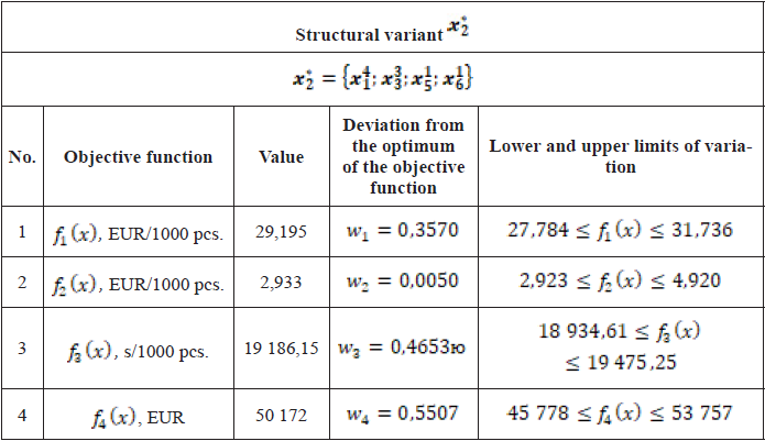
Due to the greater deviation from the optimum for the energy cost objective function, a promising direction for a study is precisely setting a higher priority for this objective function. Thus, using the method of Voichinskiy and Jansson (Voychinskiy Yanson, 1988), a higher priority for energy cost is set. For the specific problem, six pairwise comparisons must be made. The following priority vector is obtained: ![]() The values of the resulting solution are summarized in Table 4.
The values of the resulting solution are summarized in Table 4.
This solution achieves a significant improvement in energy cost (by approximately 38%), in fact, it almost achieves the optimum for the objective function, but the other objective functions significantly deteriorate. The greatest deterioration occurs for the price with an approximately 39% greater deviation from the optimum for the objective function. The average value of the deviations from the optimum of the objective functions for this solution is approximately 28%, which is an average of 2% deterioration (distance from the optimum) compared to the compromise. The occupied area is 6,15 m2, which is a deterioration (increase) compared to the compromise variant by approximately 2%.
Table 4. Structural variant with priority on energy cost
If the proposed solution satisfies the decision maker, it is selected as the solution to the problem. Otherwise, a new priority can be set.
The production rate in the compromise solution also accounts for a significant deviation from its optimum, which suggests that improvement is possible. Using the PolyOptimizer dialog system, a solution with a higher priority for production rate was studied. The given priority vector is: ![]() The solution shown in Table 5 is obtained.
The solution shown in Table 5 is obtained.
Table 5. Structural variant with priority on production rate
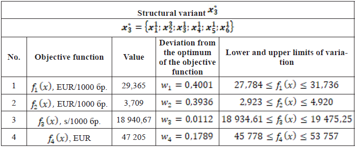
This solution significantly improves production rate by 24%. The remaining objective functions deteriorate by an average of 6% compared to ![]() The average value of the deviations from the optimum of the objective functions for this solution is approximately 25%, which is an average of 1% improvement (nearer to the optimum) compared to the compromise one. The occupied area is 6,05 m2, which is equal to the value for the compromise variant. It should be noted that here the improvement comes from the large single improvement in production rate, and not from a significant improvement in the remaining objective functions.
The average value of the deviations from the optimum of the objective functions for this solution is approximately 25%, which is an average of 1% improvement (nearer to the optimum) compared to the compromise one. The occupied area is 6,05 m2, which is equal to the value for the compromise variant. It should be noted that here the improvement comes from the large single improvement in production rate, and not from a significant improvement in the remaining objective functions.
The problem is solved with priority for the production cost. The given priority vector is: ![]() The solution shown in Table 6 is obtained.
The solution shown in Table 6 is obtained.
Table 6. Structural variant with priority on production cost
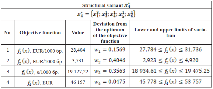
The solution found significantly improves the production cost of the system by approximately 10%, but at the expense of worsening energy cost and production rate by an average of 6%. The average value of the deviations from the optimum of the objective functions for this solution is approximately 24%, which is an average of 2% improvement compared to the compromise one. In this solution, the occupied area is 6,02 m2, i.e., 1% improvement.
The problem is also solved with the priority of the AAS price. The given priority vector is: ![]() The solution shown in Table 7 is obtained.
The solution shown in Table 7 is obtained.
Table 7. Structural variant with priority on price
The solution found improves the cost of the system by approximately 6%, at the expense of a small deterioration in the production cost and production rate by an average of 7%. The average value of the deviations from the optimum of the objective functions for this solution is approximately 28%, which is an average 2% deterioration compared to the compromise. In this solution, the occupied area is 6,05 m2, equal to the compromise variant.
4.3. Analysis of the results obtained and choice of variant
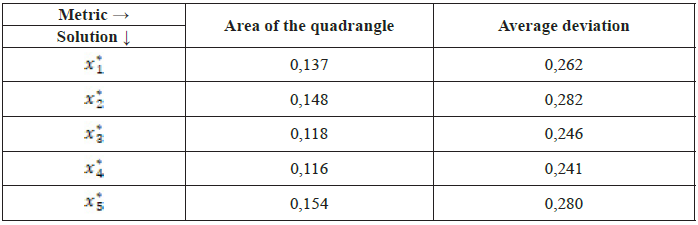
In summary, the solutions found are shown in Fig. 3. The figure is a radar diagram. Each axis corresponds to an objective function, and the vertices of the colored quadrangles correspond to the deviations from the optimum of the objective functions (in percent) for a particular solution. The ideal solution, where the deviation from the optimum for all objective functions is zero, is the central point of the radar diagram (the intersection point of the axes). Therefore, the more concentrated the quadrangle is around the center, the smaller the deviations from the optimum for the objective functions for a given solution. Thus, to compare solutions with each other, the area of the quadrangle representing the solution on the radar diagram can be used (smaller area, smaller quadrangle around the central point). Table 8 shows the area values for the individual quadrangles, along with the average deviations. The average deviation is also a useful metric, especially in special cases when figures with zero area are obtained on the radar diagram.
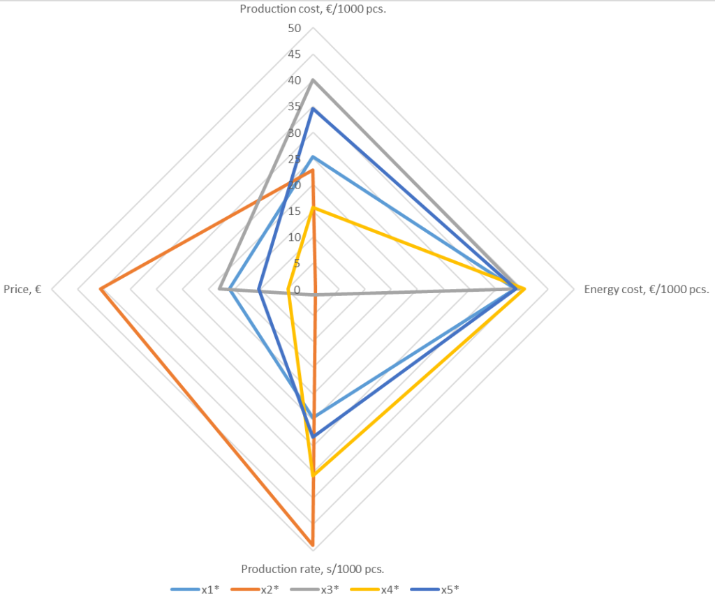
Figure 3. Radar diagram with the solutions found
Table 8. Comparison between the obtained solutions based on quadrangle area and mean deviation
The table shows that solutions ![]() and
and ![]() have too large deviations and can be rejected. The better solutions are
have too large deviations and can be rejected. The better solutions are ![]() and
and ![]() Solution
Solution ![]() gains a significant advantage due to the large improvement for one objective function, but two of the objective functions are significantly worse than the compromise solution, and the third one almost coincides in deviation. This leaves solution
gains a significant advantage due to the large improvement for one objective function, but two of the objective functions are significantly worse than the compromise solution, and the third one almost coincides in deviation. This leaves solution ![]() as a very good alternative to the compromise variant. It achieves a significant improvement in two objective functions while only one is significantly worse. However, due to the greater importance for the decision maker of energy and production rate, the compromise variant, i.e., solution
as a very good alternative to the compromise variant. It achieves a significant improvement in two objective functions while only one is significantly worse. However, due to the greater importance for the decision maker of energy and production rate, the compromise variant, i.e., solution ![]() is chosen. It is shown in Fig. 4.
is chosen. It is shown in Fig. 4.
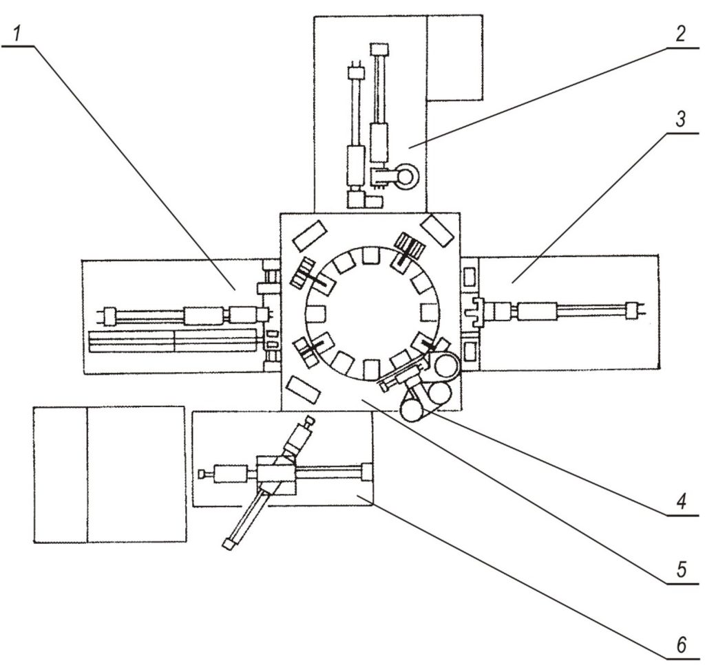
Figure 4. Automatic system for assembling the “Brush holder” unit
- Conclusion
In this work, the following important results have been achieved:
- Based on a developed technological process and the determined type, sequence and division of technological operations by work positions, the general function of the AAS is decomposed into partial functions;
- For each partial function, alternative variants are developed and their mode of operation is described.
- The set of possible structural variants is constructed using a directed graph and the definition of polyfunctional devices and compatibility;
- Criteria for evaluating the developed variants are selected;
- A mathematical model of the problem is constructed;
- A significant amount of information is collected and processed and the values of the technical and economic characteristics of the elementary devices necessary for calculating the objective and constraint functions are determined;
- The necessary information for modeling the problem is input into a dialog system for multi-criteria optimization.
- The problem of choosing an optimal structural variant of the AAS is solved under different decision-making conditions and the solutions found are analyzed;
- A variant is selected to continue in the next phase of development.
The object of future development is the experimental study of the implemented system for automatic assembly of the „Brush holder“ unit.
Acknowledgement
This study is financed by the European Union—Next Generation EU, through the National Recovery and Resilience Plan of the Republic of Bulgaria, project № BG-RRP-2.004-0005.
REFERENCES
Boothroyd, G. (2005). Assembly automation and product design. (2nd ed.). Taylor & Francis Group.
Dichev, D., Koev, H., Diakov, D., Panchev, N., Miteva, R., Nikolova, H. (2017). Automated System for Calibrating Instruments Measuring Parameters of Moving Objects. 59th International Symposium ELMAR, 219 – 224. https://doi.org/10.23919/ELMAR.2017.8124472.
Hesse, S. (1993). Montagemaschinen – Grundlagen und Prinzipien in Aufbau, Funktion, Antrieb und Steuerung montierender Maschinen. Voegel Verlag.
Holle, W. (2002). Rechnerunterstützte Montageplanung: Montageplanung und Simultaneous Engineering. Hanser Fachbuch.
Konold, P., Reger, H., Hesse, S. (1997). Angewandte Montagetechnik. Produktgestaltung, Planung, Systeme und Komponenten. Vieweg Verlagsgesellschaft.
Lotter, B. (1986). Wirtschaftliche Montage. Ein Handhabung für Elektrogerätebau und Feinwerktechnik. VDI-Verlag.
Malakov, I., Zaharinov, V., Nikolov, S., Dimitrova, R. (2023). Computer-Aided Choosing of an Optimal Structural Variant of a Robot for Extracting Castings from Die Casting Machines. Actuators, 12(9), 363. https://doi.org/10.3390/act12090363.
Mitev, P. (2024). Development of a System for the Active Orientation of Small Screws. Engineering Proceedings, 70(1), 55. https://doi.org/10.3390/engproc2024070055.
Pahl, G., Beitz, W., Feldhusen, J., Grote, K. (2007). Engineering Design a Systematic Approach. (3rd ed.). Springer.
Todorov, G., Kralov, I., Kamberov, K., Zahariev, E., Sofronov, Y., Zlatev, Z. (2024). An Assessment of the Embedding of Francis Turbines for Pumped Hydraulic Energy Storage. Water, 16(16), 2252. https://doi.org/10.3390/w16162252.
Voychinskiy, A., Yanson, E. (1988). Tehnologichnost izdeliy v priborostroenii. Mashinostroenie.